
Your Cart
Sub-Total: £0.00
£165.99


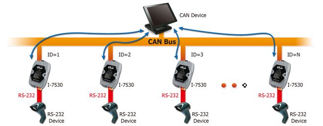
CAN (Controller Area Network) is a serial bus system especially suited to structure intelligent industry devices networks and build smart automatic control systems. The following figure shows the application architecture for I-7530 modules. The PC can be the CAN host, monitor or HMI to access/control the CAN device through the CAN network by the I-7530 Converters.
The programmable RS-232 device (For example: I-8411/I-8431/I-8811/I-8831/W-8031/W-8331/W-8731 embedded controller) can use the serial port to connect to the CAN network via the I-7530 modules. In order to use the CAN network with traditional RS-232 devices, we provide a way to achieve this purpose. The I-7530 are designed to unleash the power of CAN bus via RS-232 communication method. It accurately converts messages between CAN and RS-232 networks.
This module let you to communicate with CAN devices easily from any PC or devices with RS-232 interface.

Moreover, we expand the functionalities of I-7530 for some special application. In pair connection mode, I-7530 can be used to connect PC with other RS-232 devices at the same time. The application architecture may be as follows.
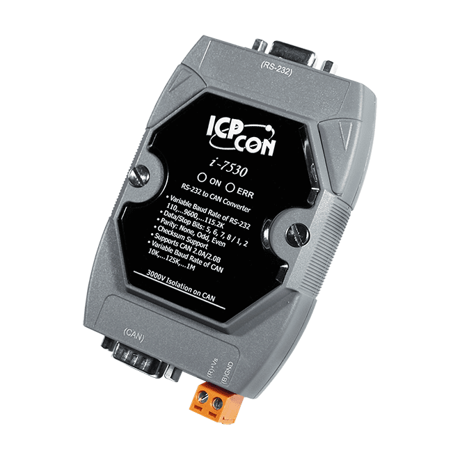
3000V isolation on CAN side
The CAN port of I-7530 is an isolated with 3000V isolation. This isolation can protect the local RS-232 devices from the damage signal coming from CAN network.
Watchdog inside
The watchdog is a hardware reset circuit to monitor the operation status. When working in harsh or noisy environment, the I-7530 may shut down by the external signal. The circuit may let the I-7530 to work continuously and never halt.
Power and Error indicator display
There are two indicators on the I-7530. The power indicator can help user to check whether the I-7530 is standby or transmitting/receiving messages. The Error indicator will be turned on when some errors occur on the I-7530.


